Gate-based computation
This example demonstrates how gate-based computation can be converted into photonic-native systems, and shows some of the tools included within Lightworks to simplify this process.
[1]:
import lightworks as lw
from lightworks import qubit, remote

try:
    remote.token.load("main_token")
except remote.TokenError:
    print(
        "Token could not be automatically loaded, this will need to be "
        "manually configured."
    )
Start by defining the target QPU which will be used for all computations within this Notebook.
[2]:
qpu = remote.QPU("Artemis")
Dual-rail encoding
To perform gate-based circuits on photonic systems such as Artemis, the qubit needs to be encoded within the properties of the photon. Due to the nature of Artemis, this needs to be through the spatial degree of freedom, by dedicating a pair of modes to each qubit in the system. Then, the state of the system is dictated by the photon probability distribution across these modes. In Lightworks, the convention used is that the first mode (the upper mode visually) corresponds to \(\ket{0}\) and the second mode corresponds to \(\ket{1}\). This is shown in the diagram below.

To simplify the process of converting between the two encodings, there are included functions for this. For example, below we convert the basic qubit states into their corresponding dual-rail encoding.
[3]:
print(f"|0> -> {lw.convert.qubit_to_dual_rail('0')}")
print(f"|1> -> {lw.convert.qubit_to_dual_rail('1')}")
|0> -> |1,0>
|1> -> |0,1>
This also scales to multi-qubit systems, for example \(\ket{01}\) in qubit encoding would be the following in a dual-rail encoding.
[4]:
print(f"|01> -> {lw.convert.qubit_to_dual_rail('01')}")
|01> -> |1,0,0,1>
Likewise, it is possible to convert back from dual-rail to qubit encoding.
[5]:
print(f"|1001> -> {lw.convert.dual_rail_to_qubit(lw.State([1, 0, 0, 1]))}")
|1001> -> |0,1>
Circuit execution
We can then move on to running circuits on Artemis. Below, a circuit is created to transform the \(\ket{00}\) state into the 2-qubit bell state \(\ket{\Phi^+} = \frac{1}{\sqrt{2}}(\ket{00}+\ket{11})\). The exact operation of this is as follows, first a Hadamard is applied to the first qubit:
\begin{equation} \text{H}_0\ket{00} = \frac{1}{\sqrt{2}}(\ket{00}+\ket{10}) \end{equation}
A CNOT gate is then applied between the first and second qubits:
\begin{equation} \text{CNOT}_{01}\frac{1}{\sqrt{2}}(\ket{00}+\ket{10}) = \frac{1}{\sqrt{2}}(\ket{00}+\ket{11}) \end{equation}
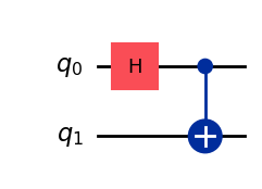
This is created within Lightworks using the code below, where a 4 mode circuit (2 qubit * 2) is defined and the relevant components added to it. The built-in heralding tools are used to automatically manage the heralding required for the implementation of a CNOT gate.
[6]:
circuit = lw.PhotonicCircuit(4)

circuit.add(qubit.H(), 0)
circuit.add(qubit.CNOT(), 0)

circuit.display()

Something to be aware of when using heralded modes is that each herald requires a dedicated mode in the photonic processor, which means that circuits can require more resources than may initially appear. For example, in the circuit above, there are 4 input modes and 2 heralded modes, meaning the actual circuit size is 6 modes. The size of circuit can be monitored using the n_modes attribute. Likewise, input_modes can be used to check the number of user specified modes in a circuit.
[7]:
print(f"Required modes = {circuit.n_modes}")
print(f"Input modes = {circuit.input_modes}")
Required modes = 6
Input modes = 4
The input state is then defined, using the conversion function to switch from qubit to dual-rail encoding.
[8]:
in_state = lw.convert.qubit_to_dual_rail("00")
print(in_state)
|1,0,1,0>
Lastly, the CNOT gate above requires post-selection to function correctly, in which it is required only 1 photon is measured across each pair of modes. This can be applied using the PostSelection object in Lightworks, as is shown below.
[9]:
post_selection = lw.PostSelection()
post_selection.add((0, 1), 1)
post_selection.add((2, 3), 1)
The sampler task is then created and can be run on the target QPU.
[10]:
sampler = lw.Sampler(circuit, in_state, 10000, post_selection=post_selection)
[11]:
job = qpu.run(sampler)
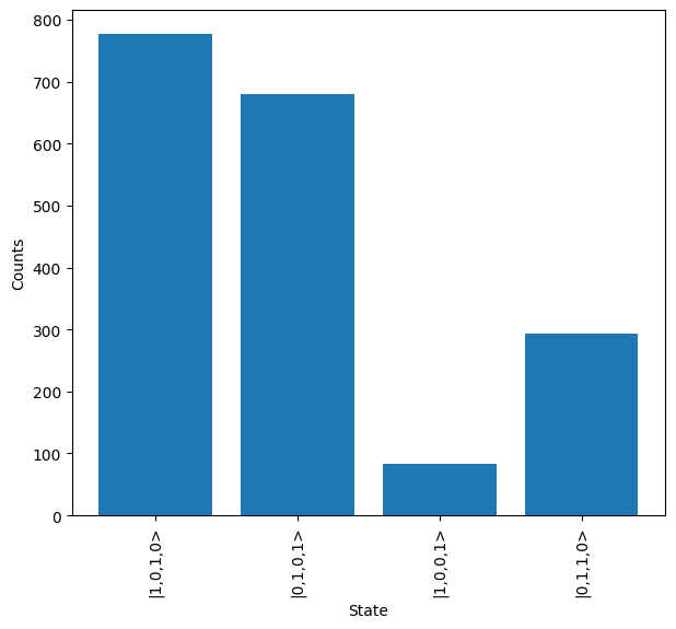
Once complete, the results from the job are retrieved and plotted. These will be in a dual-rail encoding by default, which may make them slightly tricky to interpret.
[12]:
job.wait_until_complete()

results = job.get_result()
results.plot()
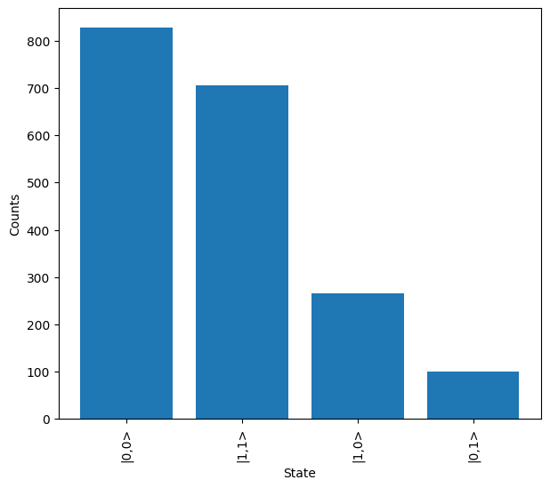
To resolve this, we can use the results map method and dual_rail_to_qubit function to convert all results into the qubit encoding. Once complete, it can be seen how the states measured are now the 3-qubit outputs expected from the system.
[13]:
conv_results = results.map(lw.convert.dual_rail_to_qubit)
conv_results.plot()
Qiskit conversion
To simplify the process of running gate-based systems on Artemis, a qiskit converter is included within Lightworks for the conversion of a qiskit QuantumCircuit into the Lightworks equivalent.
This requires the importing of the qiskit module. This may need to be installed if not already completed - pip install lightworks[qiskit] can be used to ensure all the correct dependencies are installed.
[14]:
import qiskit
Then, a quantum circuit is built. In this case, we recreate the bell state circuit from above.
Note
There are some limitations as to what can be converted within Lightworks, and circuits which contain mid-circuit measurement of writing of data to classical bits are not currently compatible.
[15]:
qc = qiskit.QuantumCircuit(2)

qc.h(0)
qc.cx(0, 1)

qc.draw(output="mpl")
[15]:
This circuit is then converted using the qiskit converter, it can be seen how this produces the same circuit as the previous example. In this function there is an allow_post_selection option which controls whether to allow post-selected versions of gates where possible (rather than just heralding). This defaults to False, but we recommend setting to True in most-cases as post-selected gates tend to have lower resource requirements - the converter uses an algorithm to ensure post-selection is only used where possible. When this option is True, a PostSelection object is returned by the conversion function which needs to be supplied on configuration of the Sampler.
Note
Some care needs to be taken if this circuit is modified further within Lightworks, as any other two-qubit gates will break the post-selection and cause significant errors. If intending to modify then use allow_post_selection=False.
[16]:
circuit, post_selection = qubit.qiskit_converter(qc, allow_post_selection=True)

circuit.display()

The sampler is then created and the job run on the target QPU.
[17]:
sampler = lw.Sampler(circuit, in_state, 10000, post_selection=post_selection)
[18]:
job = qpu.run(sampler)
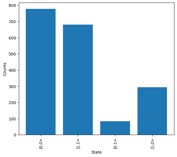
Once complete, again the results are downloaded, and then the results re-mapped and plotted.
[19]:
job.wait_until_complete()

results = job.get_result()
This produces a set of results which should look similar to the previous run in which qiskit conversion was not used.
[20]:
conv_results = results.map(lw.convert.dual_rail_to_qubit)
conv_results.plot()